TP 5: Visualizing the robotized factory model through interfaces
Overview
In the previous practical session, we modelled the structure of the robotized factory for which we want to develop a simulator. We created an object model of the factory. In this session, we will modify this model to make it visualizable through a graphical interface provided to you. To do so, your model must implement the Java interfaces provided by this graphical interface.
The graphical interface is very simple. The only thing it can do is display two-dimensional (2D) geometric shapes of rectangular, oval, or polygonal forms, in various colours, with different line styles (dashed and thickness) on a drawing canvas.
As seen in class, an interface defines a perspective or a property descriptor for the classes that implement it. Thus, the provided graphical interface provides Java interfaces specifying a simple 2D shape viewpoint. Each component of the robotized factory can indeed be represented as a 2D shape on a canvas. Therefore, the classes in your model need only implement the provided 2D shape interfaces for the graphical interface to display them.
This set of interfaces provided by the graphical interface serves as a contract between the model and the graphical interface for displaying the model. This way of integrating different software components is a common programming practice.
In this lab, you will learn to:
- Integrate the canvas viewer library and configure the project
- Expose model elements as
Figure/Canvasimplementations - Launch and verify the graphical visualization
The graphical interface for shape visualization
-
Download the graphical interface library for shape visualization (canvas viewer), which can be found here. This library, named
canvas-viewer.jar, is essentially a set of compiled Java classes (.classfiles) that can be used by other Java applications. -
Open the
canvas-viewer.jarfile with a file compression utility like 7-Zip. You will see that it is simply an archive containing.classfiles arranged in the same directory structure as the class packages. You will also find.javafiles, allowing you to view the source code of the graphical interface and even set breakpoints to understand what happens using a debugger.
Configuring the simulator project to use the graphical interface library
-
In the project or package browser in Eclipse, select your simulator project, right-click, and click
New>Folderto create a directory namedlibs. -
Move the
canvas-viewer.jarfile to this directory (you can also directly drag and drop the file from your operating system's file browser into the project browser in Eclipse). -
Select your simulator project, right-click, and click
Properties. -
In the dialogue box that appears, select the
Java Build Pathsection, then theLibrariestab on the right side of the window. SelectClasspath, then click theAdd Jars...button and navigate to thecanvas-viewer.jarfile you added in thelibsdirectory.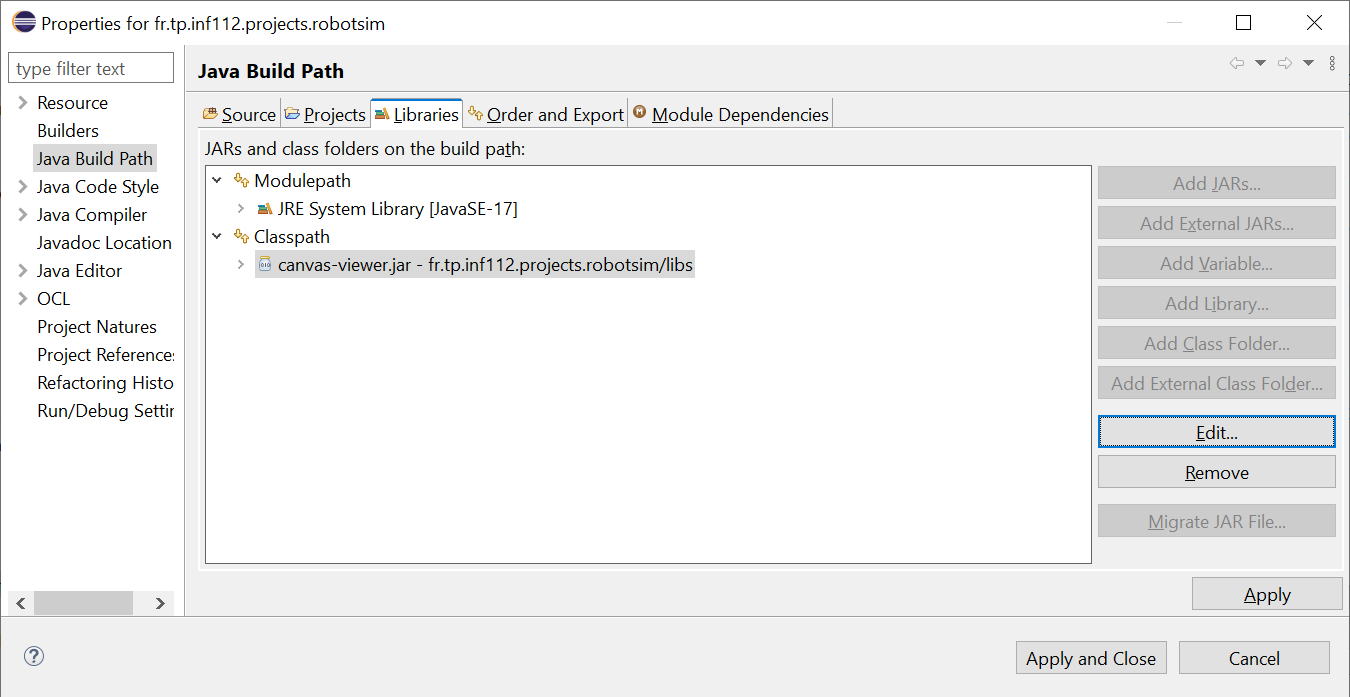
-
In the package explorer (or project browser), expand the
Referenced Librariesbranch. You will see thecanvas-viewer.jarlibrary you just added to the project. -
You will also see the packages provided by this library. Open the packages
fr.tp.inf112.projects.canvas.modelandfr.tp.inf112.projects.canvas.model.impl.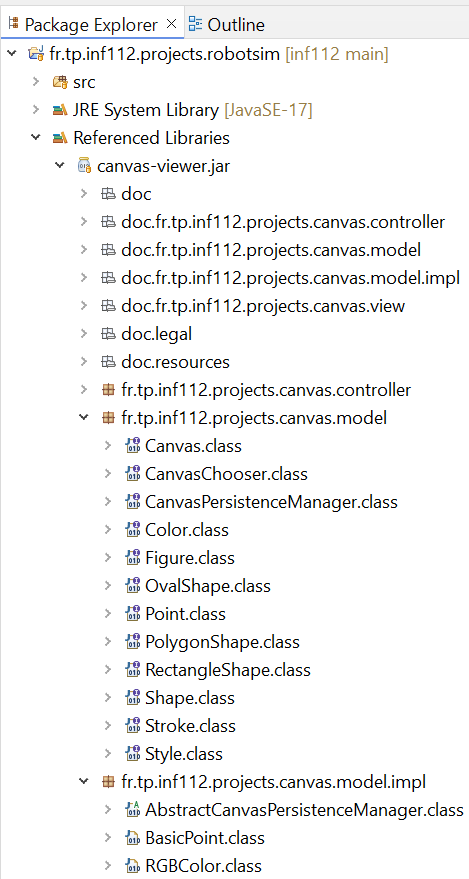
-
Examine the contents of these packages. In
fr.tp.inf112.projects.canvas.modelyou will find interfaces such asCanvas,Figure,Style, andShape.-
The
Canvasinterface describes canvas properties such as its name, width, height, and a collection of shapes to display on the canvas. -
The
Figureinterface describes 2D shape properties such as its name, position on the canvas ($x$ and $y$ coordinates), style (characterized by colour and contour), and shape, as described by theShapeinterface. -
The graphical interface can display only three types of shapes, whose properties are described by the sub-interfaces
RectangleShape,OvalShape, andPolygonShape.
To make them easier to use, all these interfaces include Javadoc documentation explaining the various methods required by the interfaces.
-
Note 1: In
fr.tp.inf112.projects.canvas.viewyou will find the classes that implement the graphical interface used to visualize your robotized factory model. Understanding these classes is unnecessary, as graphical interfaces are not part of this course curriculum.
Implementing the canvas interfaces with the robotized factory model
To display your model in the graphical interface, you must determine which interfaces the classes of your robotized factory model should implement. For example, the factory, which consists of a layout where the components of the factory are positioned, can be seen as a Canvas. Similarly, any component of the robotized factory can be represented by a 2D geometric shape (or figure).
-
Thus, your abstract
Componentclass must implement theFigureinterface:public abstract class Component implements Figure
Name and position of the shape on the canvas
- The
Figureinterface requires a name (getName()method) for the shape, displayed on the top-left corner of the shape on the canvas. It also requires the coordinates of the shape to know where to draw it on the canvas.
Style of the shape
- The
Figureinterface also requires knowing the display style of the shape. This style is characterized by a background colour for the shape (getBackgroundColor()method) and the contour characteristics (thickness, dash, colour, as described by theStrokeinterface).
Shape of the shape
As mentioned earlier, the graphical interface can only draw shapes of rectangular (RectangleShape), oval (OvalShape), or polygonal (PolygonShape) forms.
-
For each concrete subclass of the
Componentclass, you must determine the desired shape and define implementation classes for these shapes. -
Then, each component must define the
getShape()method of theFigureinterface to return an instance of the implementation corresponding to the chosen shape for the component.For example: Since the robots in the factory are circular, your
Robotclass will return an instance of an implementation class ofOvalShape, while theRoomorAreaclasses, corresponding to rectangular components, will return instances of an implementation class ofRectangleShape. -
Do the same for each class component of your model that needs to be visualized by the graphical interface, except for the class representing the robotized factory, which will be considered rectangular.
The canvas
Indeed, this class should instead implement the Canvas interface, which represents the container for shapes. Note that the Canvas interface specifies a Collection<Figure> getFigures() method. Since all the factory components implement the Figure interface, you can directly return the attribute of your Factory class containing the components.
-
However, you may need to cast this reference as follows:
public Collection<Figure> getFigures() {
    return (Collection) components;
}
Launching the graphical interface
-
Examine the
CanvasViewerclass in thefr.tp.inf112.projects.canvas.viewpackage of the graphical interface library (filecanvas-viewer.jar). One of the constructors of this class takes a single parameter: an instance of a class implementing theCanvasinterface. This is the constructor you will use to launch the graphical interface. -
To this end, create a class named
SimulatorApplicationto represent the simulator application linking the model and the graphical interface. -
In this class, create a
main()method. -
In this method, instantiate a factory model as in the previous session, which contains:
-
3 rooms, each containing a workspace with a production machine,
-
3 robots, and
-
1 charging station.
-
-
Then, instantiate the
CanvasViewerclass provided by the graphical interface, providing it with the factory you just created. -
Run the
main()method. -
Verify that your model is correctly displayed in the graphical interface, as illustrated by the following figure.
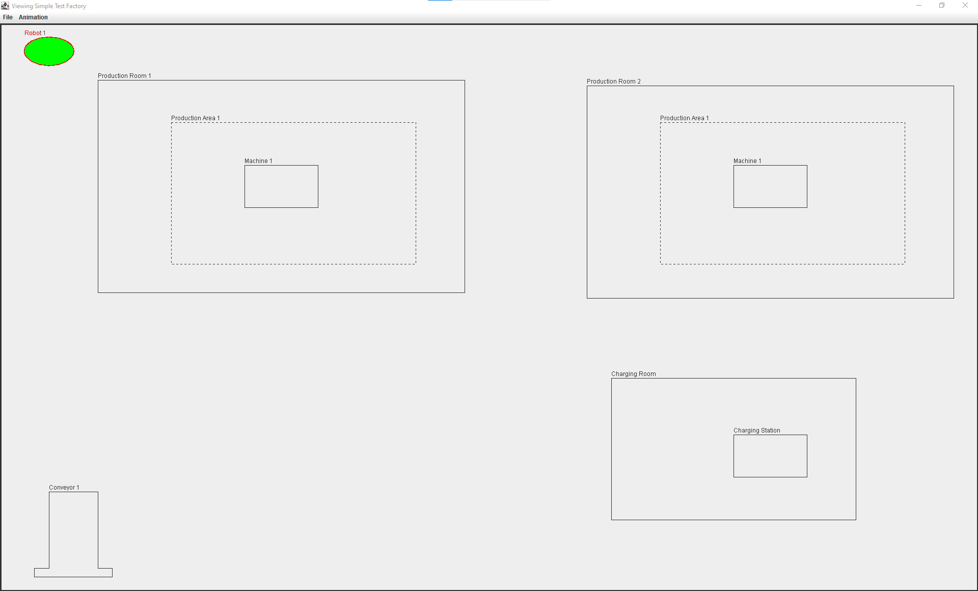
Note 2: It should be noted that none of the actions defined by the graphical interface menus will work (they will be disabled) except for the action of quitting the application. These actions will be defined in the next practical session when you implement the controller interface of the model-view-controller design pattern, which we will explain in class first.